Match the circuit components with their schematic diagrams. – In the realm of electronics, understanding the relationship between circuit components and their schematic representations is paramount. This guide delves into the functions and purposes of various circuit components, the significance of schematic diagrams, and the art of matching components to their corresponding symbols.
Schematic diagrams serve as blueprints for circuit design, providing a visual representation of the electrical connections and components. By mastering the ability to match circuit components to their schematic symbols, individuals gain a deeper comprehension of circuit behavior and enhance their troubleshooting skills.
Circuit Components: Match The Circuit Components With Their Schematic Diagrams.

Circuit components are the basic building blocks of electronic circuits. They can be classified into two main types: passive and active. Passive components do not amplify or generate signals, while active components do. Some common examples of passive components include resistors, capacitors, and inductors.
Some common examples of active components include diodes, transistors, and integrated circuits (ICs).
Resistors
Resistors are used to control the flow of current in a circuit. They are made of a material that has a high resistance to the flow of electricity. The resistance of a resistor is measured in ohms (Ω). The higher the resistance, the less current will flow through the resistor.
Capacitors
Capacitors are used to store electrical energy. They are made of two metal plates that are separated by an insulating material. When a voltage is applied to a capacitor, the plates become charged. The amount of charge that a capacitor can store is determined by its capacitance, which is measured in farads (F).
The higher the capacitance, the more charge the capacitor can store.
Diodes, Match the circuit components with their schematic diagrams.
Diodes are used to allow current to flow in only one direction. They are made of a semiconductor material that has a different resistance to the flow of electricity in each direction. When a voltage is applied to a diode in the forward direction, the diode will conduct current.
When a voltage is applied to a diode in the reverse direction, the diode will block current.
Transistors
Transistors are used to amplify or switch signals. They are made of a semiconductor material that has three terminals: the base, the emitter, and the collector. When a voltage is applied to the base of a transistor, the transistor will conduct current between the emitter and the collector.
The amount of current that flows through the transistor is determined by the voltage applied to the base.
Schematic Diagrams

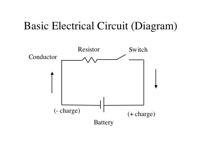
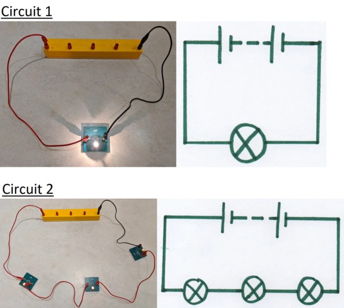
Schematic diagrams are used to represent electrical circuits. They use symbols to represent the different components in the circuit. The symbols are standardized so that they can be easily understood by anyone who is familiar with electronics. Schematic diagrams are used for a variety of purposes, including designing, troubleshooting, and repairing circuits.
Symbols
The symbols used in schematic diagrams are standardized so that they can be easily understood by anyone who is familiar with electronics. The symbols are typically based on the physical appearance of the component. For example, the symbol for a resistor is a rectangle with two lines inside.
The symbol for a capacitor is a circle with two lines inside. The symbol for a diode is a triangle with a line inside.
Layout
The layout of a schematic diagram is important for making it easy to understand. The components in the circuit are typically arranged in a logical order, such as from left to right or from top to bottom. The connections between the components are shown with lines.
The lines are typically drawn in a straight line, but they can be bent or curved to make the diagram easier to read.
Matching Components to Diagrams

Matching circuit components to their corresponding schematic symbols is an important skill for anyone who works with electronics. It is a good way to test your understanding of the different components and their functions. There are a number of online resources that can help you learn how to match components to diagrams.
Interactive Table
One of the best ways to learn how to match components to diagrams is to use an interactive table. An interactive table allows you to select a component from a list and then see its corresponding schematic symbol. You can also click on the schematic symbol to see more information about the component.
Frequently Asked Questions
What is the purpose of a schematic diagram?
A schematic diagram provides a visual representation of the electrical connections and components in a circuit, serving as a blueprint for circuit design and analysis.
How can I improve my ability to match circuit components to their schematic symbols?
Practice and repetition are key. Engage in exercises that involve matching components to symbols, and refer to resources that provide clear explanations and examples.
What are some common circuit components?
Resistors, capacitors, diodes, transistors, and integrated circuits are among the most commonly used circuit components.